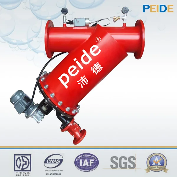
Structure and working principle
Automatic brushaway filter is composed of the drive mechanism, the control circuit (including the pressure switch), filter components, cleaning device, connecting flanges and other major component parts.It cleans sewage by the drive motor and the electric valve automatically, the operation mode is automatic operation (option:manual operation), with timing control or pressure difference control. Its automated part is controlled by reliablePLC programmable controller.
Water enters into the filter, the mechanical impurities are intercepted.When the impurities accumulate for a period, reaches 0.05MPa, then the differential pressure switch will send signal, while the PLC command is issued, transmission motor starts, the drain valve opens, the impurities deposited on the filter is brushed away,and drain out.The whole process is without personnel, without downtime. Besides, the device also has the function of timing and manual cleaning to ensure that the outlet water is safe under any circumstances.
Two types of cleaning method
Automatic control: there are two types:timing control and pressure difference. Set the filtration time on the filter timer, when it reaches the setting time, the brush will start cleaning sewage,discharge time is also set by timer; while the system pressure control system with real-time user-defined pressure compared when the system pressure reaches the set pressure difference, the filter will start cleaning sewage, sewage discharge time set by the timer.The whole system returns to its initial state, prepare for the next filtration step.
Manual control: Press the manual button on the control panel, filters will start cleaning.
Feature
Filter precision from 100um to 3500um,big filter area,high sewage carrying capacity,customized product.
Simple turn-of-a-handle cleaning of the filter screen,adjust the parameter of the automatic cleaning system.Automatic cleaning.
Has motor overload protection, which can effectively protect the motor.
Eliminates the need for turning off the water and extracting the filter screen for rinsing.No interruption of the process water flow during cleaning,Low pressure loss:less than 1%.
Easy to maintenance,installation and disassemble.
Flange connections to the user’s pipeline, national standard flange, versatility.
Technical Parameters
1. Treatment effectiveness
Filter precision: customized
Filtration efficiency: 99%;
Initial pressure loss: ≤0.015Mpa.
2. Inlet Water Quality
Working pressure: 1.0 / 1.6 / 2.5Mpa;
System pressure: ≥0.4Mpa;
Working temperature: 1 ℃ -90 ℃;
Working environment temperature: 1 ℃ -50 ℃;
Relative Humidity: <95%.
3. Operating parameters
Mean time between failures:> 60,000 hours;
Design life: 20 years for shell; 8 years for electrical parts.
Power: 0.2-0.6kw
Operating voltage: 220V ~ 380V ± 10%, 3-phase, 50 / 60Hz;
Safety insulation voltage: 5000V.
Size ChartY type automatic brushaway filter
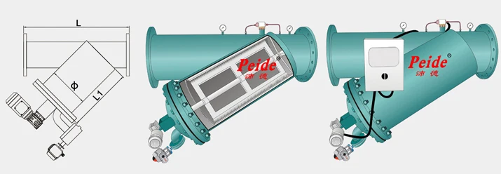
| Model | Inlet&outlet | Max flow rate | dimension | drain | motor | ||
| mm | T/H | L | φ | L1 | mm | Kw/r/min | |
| SLQ-2Y | 50 | 19 | 600 | 159 | 300 | 25 | 0.18/1400 |
| SLQ-3Y | 80 | 50 | 600 | 159 | 300 | 25 | 0.18/1400 |
| SLQ-4Y | 100 | 80 | 700 | 159 | 300 | 40 | 0.18/1400 |
| SLQ-5Y | 125 | 125 | 750 | 219 | 350 | 40 | 0.18/1400 |
| SLQ6Y | 150 | 180 | 800 | 275 | 450 | 50 | 0.18/1400 |
| SLQ-8Y | 200 | 320 | 850 | 325 | 525 | 50 | 0.18/1400 |
| SLQ-10Y | 250 | 490 | 900 | 377 | 650 | 50 | 0.18/1400 |
| SLQ-12Y | 300 | 710 | 950 | 426 | 700 | 65 | 0.18/1400 |
| SLQ-14Y | 350 | 970 | 1170 | 478 | 820 | 65 | 0.18/1400 |
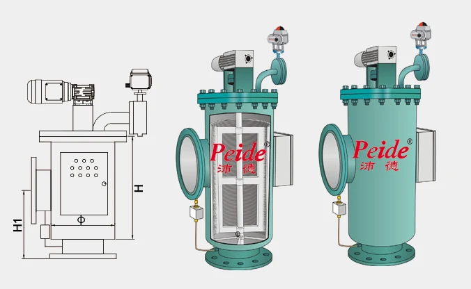
| Model | Inlet&outlet | Max flow rate | dimension | drain | motor | ||
| mm | T/H | L | φ | L1 | mm | Kw/r/min | |
| SLQ-2F | 50 | 19 | 300 | 159 | 225 | 25 | 0.18/1400 |
| SLQ-3F | 80 | 50 | 300 | 159 | 270 | 25 | 0.18/1400 |
| SLQ-4F | 100 | 80 | 300 | 159 | 300 | 40 | 0.18/1400 |
| SLQ-5L | 125 | 125 | 350 | 219 | 365 | 40 | 0.18/1400 |
| SLQ6F | 150 | 180 | 600 | 273 | 450 | 50 | 0.18/1400 |
| SLQ-8F | 200 | 320 | 700 | 325 | 560 | 50 | 0.18/1400 |
| SLQ-10F | 250 | 490 | 700 | 377 | 700 | 50 | 0.18/1400 |
| SLQ-12F | 300 | 710 | 1000 | 426 | 800 | 65 | 0.18/1400 |
| SLQ-14F | 350 | 970 | 1000 | 478 | 940 | 65 | 0.18/1400 |
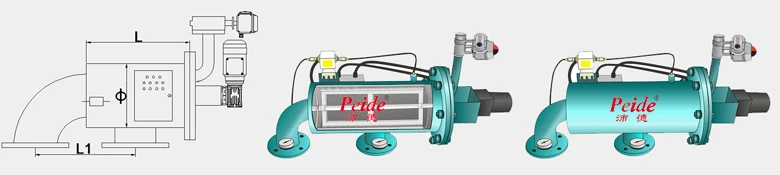
| Model | Inlet&outlet | Max flow rate | dimension | drain | motor | ||
| mm | T/H | L | φ | L1 | mm | Kw/r/min | |
| SLQ-2L | 50 | 19 | 300 | 159 | 250 | 25 | 0.18/1400 |
| SLQ-3L | 80 | 50 | 300 | 159 | 250 | 25 | 0.18/1400 |
| SLQ-4L | 100 | 80 | 300 | 159 | 250 | 40 | 0.18/1400 |
| SLQ-5L | 125 | 125 | 350 | 219 | 275 | 40 | 0.18/1400 |
| SLQ6L | 150 | 180 | 450 | 273 | 325 | 50 | 0.18/1400 |
| SLQ-8L | 200 | 320 | 525 | 325 | 360 | 50 | 0.18/1400 |
| SLQ-10L | 250 | 490 | 650 | 377 | 425 | 50 | 0.18/1400 |
| SLQ-12L | 300 | 710 | 700 | 426 | 450 | 65 | 0.18/1400 |
| SLQ-14L | 350 | 970 | 820 | 478 | 520 | 65 | 0.18/1400 |

Installation Points for attention
1, The check valve must be installed to avoid back pressure or backwater phenomenon, caused by inward deformation of filter screen.
2,For the operating pressure above 0.8MPa or more, the gate valve must be installed on the sewage lines, it will reduce the pressure loss, and the impact after the drainage. (you may ask for specific advisory from suppliers)
3,Prohibit the sudden pressure relief. For example, the normal working pressure is 1.3MPa, shut down suddenly,and open the outlet piping manifold pressure relief valve, it will have a huge opening moments of pressure will cause filter damage.
4, Make sure that the filter works within the normal operating range, banned from overpressure, over flow rate.
5,When the equipment alarms, if you can not handle at once, you should immediately open the bypass valve. Otherwise, thefilter can not hold pressure,andit also affectproduction.
6, For the filter with control box, you must ensure the continuous power supply for control box . Otherwise, it will cause filter clogging, the system hold pressure, impact production, and even cause filter damage. Re-transmission may occur because of filter clogging motor tripping the alarm. Power interruption is recommended to open the bypass valve, close the filter inlet and outlet valves and control box power switch. Filter restart when power on.
How to install
a. equipment can not be installed in the negative pressure zone.
b. noted the direction of the water flow.
c. By-pass conduit is preferably provided so that the normal operation of the filter for cleaning or failure does not affect the system;
d.Pipeline should be floated over 5m,supported by steel or concrete barrier.
e. When the filter installed with other water processor equipment,this filter should be installed before the inlet.
How to choose the suitable model


- Product Listing Policy - Intellectual Property Policy and Infringement Claims
- Related Links
- Privacy Policy
- Terms of Use
ICP License: 浙ICP备2023052164号 © Coowor.com. All rights reserved.
Tel: +86 10 65447649 E-mail: coowor@coowor.com
Copyright © Hangzhou Coowor Network Technology Co., Ltd. All Rights Reserved.